PID Control 18-07-2023
Have you ever wondered how machines and robots are able to maintain their position or speed? One of the key components in achieving this is through a control system called PID control. PID control is a widely used technique in the field of engineering and automation that allows machines to maintain a desired setpoint despite external disturbances or changes in the system.
PID control is a feedback control mechanism used in engineering and industrial processes to regulate a system's output based on its error or the difference between the desired setpoint and the measured value. The name "PID" comes from the three components of the control system: Proportional, Integral, and Derivative.
In this article, we will delve deeper into each component of the PID control system, explore the mathematics behind it, and discuss practical applications of the technique. Additionally, we will explain how to tune a PID controller to optimize its performance and highlight the advantages and limitations of PID control. By the end of this article, you will have a solid understanding of how PID control works, and how it is used in various industries to enhance the accuracy, efficiency, and stability of systems.
Understanding the three components of a PID controller can be a bit challenging, especially for those new to the field of engineering and control systems. However, analogies can help make the concept more relatable and easier to grasp. In this case, we will use three analogies to explain each component of a PID controller: Proportional (P), Integral (I), and Derivative (D) control. By relating these concepts to everyday scenarios, we can develop a better understanding of how PID control works, and how it can be used to optimize the performance of a wide range of systems.
Proportional (P) Control:
Think of P control as a person driving a car towards a destination. The driver adjusts the speed of the car based on the distance between the car and the destination. If the car is far away, the driver accelerates to get closer to the destination. If the car is too close, the driver slows down. In a similar way, P control adjusts the output of a system based on the current error between the measured value and the desired setpoint. The further away the system is from the setpoint, the stronger the adjustment.
Integral (I) Control:
Imagine a person carrying a heavy backpack while walking up a hill. The weight of the backpack causes the person to slow down, but the person can compensate by taking larger steps or using more force to push forward. Similarly, I control considers past errors between the measured value and the setpoint and adjusts the output of the system accordingly. The larger the accumulated error over time, the stronger the adjustment.
Derivative (D) Control:
Picture a skateboarder going down a ramp. As the skateboarder approaches the bottom of the ramp, they anticipate the changes in slope and adjust their body position to maintain balance. Similarly, D control predicts future errors between the measured value and the setpoint and adjusts the output of the system based on the rate of change of the error. The faster the error is changing, the stronger the adjustment.
Mathematics:
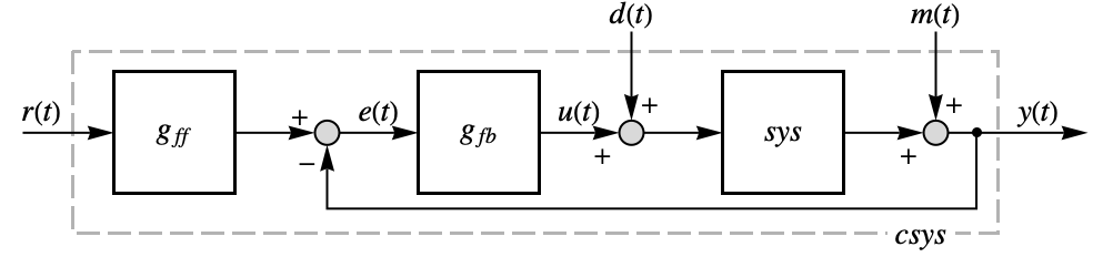
The ideal PID controller effectively computes the control signal u(t) through with proportional, integral, and derivative terms. With thanks to Mathematica, the following diagram explains
The Proportional element consists of
Larger proportional gain results in larger changes in response to the error, and thus affects the speed at which the controller can respond to changes in the system.
The Integral element consists of
Integral control goes a step further than proportional gain, as it is proportional to not just the magnitude of the error signal but also the duration of the error.
And, finally, the Derivative element consists of
Derivative control attempts to reduce the overshoot and ringing potential from proportional and integral control. It determines how quickly the circuit is changing over time (by looking at the derivative of the error signal) and multiplies it by Kd to produce the derivative response.
Practical use:
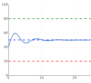
In practical use, Proportional is dependent upon the present error, Integral is dependent upon the accumulation of past error, and Derivative is the prediction of future error. Through proper setting of the controls in a PID circuit, relatively quick response with minimal overshoot (passing the set point value) and ringing (oscillation about the set point value) can be achieved. Improper setting of the PID controls can cause the circuit to oscillate significantly and lead to instability in control. It is up to the user to properly adjust the PID gains to ensure proper performance.
In general the gains of P, I, and D will need to be adjusted by the user in order to best servo the system. While there is not a static set of rules for what the values should be for any specific system, following the general procedures should help in tuning a circuit to match one’s system and environment. In general, a PID circuit will typically overshoot the setpoint value slightly and then quickly damp out to reach the SP value.
Example:
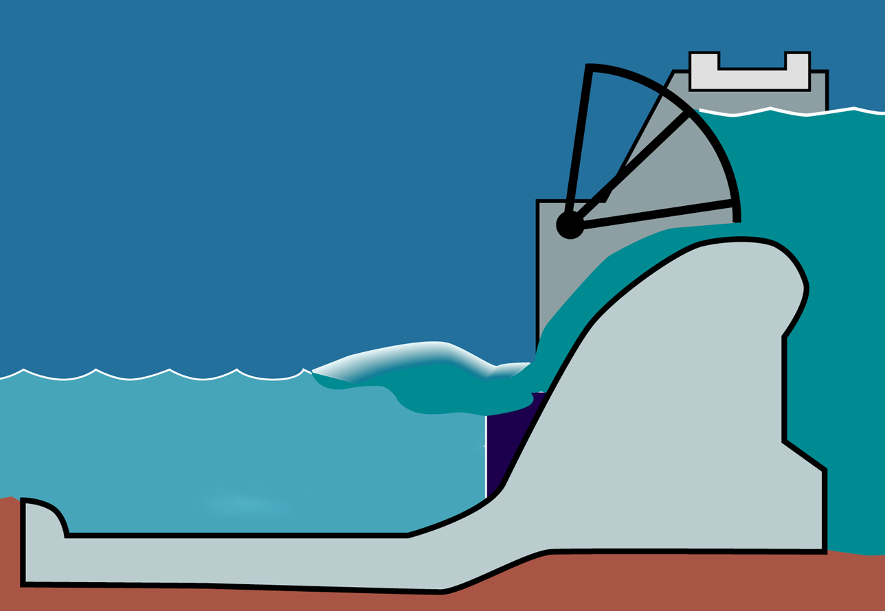
In this example, we will explore how PID control can be used to manage the water level in a dam using a sluice gate. A sluice gate is a mechanism that can be used to control the amount of water that flows out of a dam. This is important because if the water level rises too high, it can cause flooding, and if it falls too low, it can affect the supply of water downstream. Using a PID controller, we can set a desired water level (setpoint) between 20% and 80%, and adjust the position of the sluice gate accordingly to regulate the water level. The PID controller uses three components: Proportional (P), Integral (I), and Derivative (D) control, each with adjustable terms. In this example, you should be able to get a feel for how these variables affect the ability of the PID controller to maintain a stable water level in the dam.
Water level: %
set point: %
PID gains
Kp:
Ki:
Kd: